HART Overview
This is the first of what is planned to be a many part series detailing the history, protocol and design best practices for WirelessHART™.
Before diving into the details of WirelessHART, let’s unpack the HART® standard upon which WirelessHART was built. HART technology has opened up a wealth of digital process, maintenance, and diagnostic information. This information is valuable throughout the plant lifecycle from design, to installation and configuration, through operation, and finally maintenance. The HART communication protocol was designed to meet the following requirements for industrial applications:
- Reliability
- Plant availability
- Security
- Low maintenance
- Cost effectiveness
The whole point of a sensor is to be monitored; sensor data could include temperature, flow, vibration, level, pH, and pressure measurements. Sensors gather process information and often use current loops to carry process instrumentation to proportional-integral-derivative (PID) controllers, SCADA systems, programmable logic controllers (PLDs), or distributed control systems (DCS). Current loops formed the industry de facto standard for interconnecting these devices because they met the design requirements listed above.
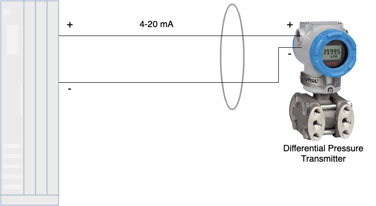
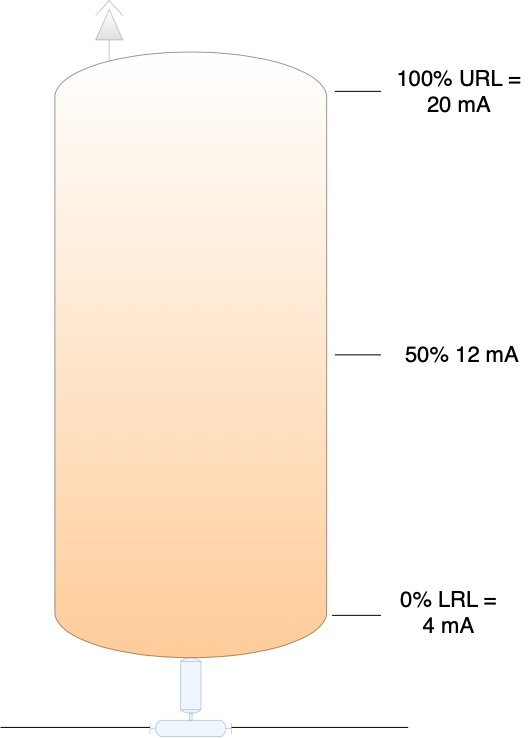
Current loops, often referred to as 4 – 20 mA loops, are analog circuits used for electronic signaling. The range of values to be measured is mapped to a scale between 0 – 100%. A value of 4 mA is assigned to the lower range limit (LRL) and a value of 20 mA is assigned to the upper range limit (URL). The physical loop consists of twisted pair conductors capable of transmitting a distance up to 1000 m using 18 gauge wire. In addition to being cost effective, the current loop naturally allows self-monitoring where a reading of 0 mA, or no current, indicates a break in the loop. Simply stated, any reported values outside the range of 4 – 20 mA indicate fault. Current loops provide some flexibility as current measured in milliamperes could easily be converted into voltage using Ohm’s law (V=IR). In the image below, an empty tank with 0% product is set to 4 mA. At 50% capacity the output current is 12 mA and at 100% tank capacity the output current is 20 mA.
An analog-to-digital (A/D) converter with 16-bit (or 216) precision can report the range of values measured by an analog sensor in 65,535 discrete increments. This granularity allows a 1000 L tank to be measured in increments of 0.015 L (or 1000 divided by 65,535). While impressive, an analog current loop is limited with respect to the amount of instrumentation data it can provide. Furthermore, analog signals only flow and send information in one direction.
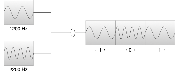
The Bell 202 communication standard was released in 1976. Bell 202 modulation uses audio frequency-shift keying (AFSK) to transmit a 1200 Hz tone to represent binary value of ‘1’ and a 2200 Hz tone to represent a binary value of ‘0’.
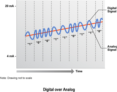
You’ve likely used this technology without knowing. Bell 202 is used to transmit callerID information over the POTS lines in the telephone network. POTS uses a direct current operating at 48 VDC to transmit analog voice signals over a pair of copper wires. Bell 202 allowed a digital signal to be superimposed on top of the analog wave form thereby conveying additional information. Superimposing a digital signal along with an analog signal does not impact the analog wave. Each crest of the overlaid digital wave form is equally matched with a corresponding trough. The two halves of the sine wave cancel each other out resulting in no effect on the analog signal.
Bell 202 was eventually adopted for subsea oil and gas production control systems in the mid 1980s, later becoming the foundation for the HART Communication Protocol. HART was originally developed by Rosemont Communications Inc and uses a hybrid analog-digital signal. HART is an acronym for Highway Addressable Remote Transducer. In 1986 it was made into an open standard and the HART Communication Foundation (www.hartcomm.org) was later founded in 1993. In 2015, the HART Communication Foundation merged with the Fieldbus Foundation as a single entity to become the FieldComm Group (fieldcommgroup.org). The FieldComm Group now maintains the HART standard.
Previously, each instrumentation device required its own dedicated current loop. HART allowed multidrop loops with multiple instrumentation nodes tapped into a single loop – think of something along the lines of thick ethernet with vampire taps. Small networks could form with multiple devices. HART revision 3 through 5 allowed an address range 1 to 15. HART revision 6 allowed addresses 1 through 63 and HART revision 7 allowed addresses 0 to 63 with each instrument requiring a unique address. Two masters are allowed on the loop, the primary master is the control system or other host application. The secondary master is reserved for the handheld terminal used in the field to attach to the loop for communication with instrumentation devices for configuration, diagnostics, or maintenance.

The structure of a HART packet appears as follows:
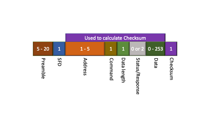
Preamble – Newer devices implement a five byte preamble (all ‘FF’s). Masters are responsible for backward support. Master communication to a new device starts with the maximum preamble length (20 bytes) and is later reduced once the preamble for the current device is determined.
Start frame delimiter (SFD) – Contains the Master number and specifies that the communications packet is starting.
Address – Specifies slave/master and indicates burst mode (long format uses 5 bytes).
Command – Numerical value for the command to be executed.
Length of Data Field – Indicates length of the Data Field in bytes.
Status/Response – Used when responding to a Master. Unused when sent from Master.
Data – Data associated with command to be executed. BACK and ACK must contain at least two data bytes.
Checksum – XOR of all bytes following the SFD byte and ending with the last byte of the data field.
Slàinte!