Stop Designing Wi-Fi for Your Weakest Device
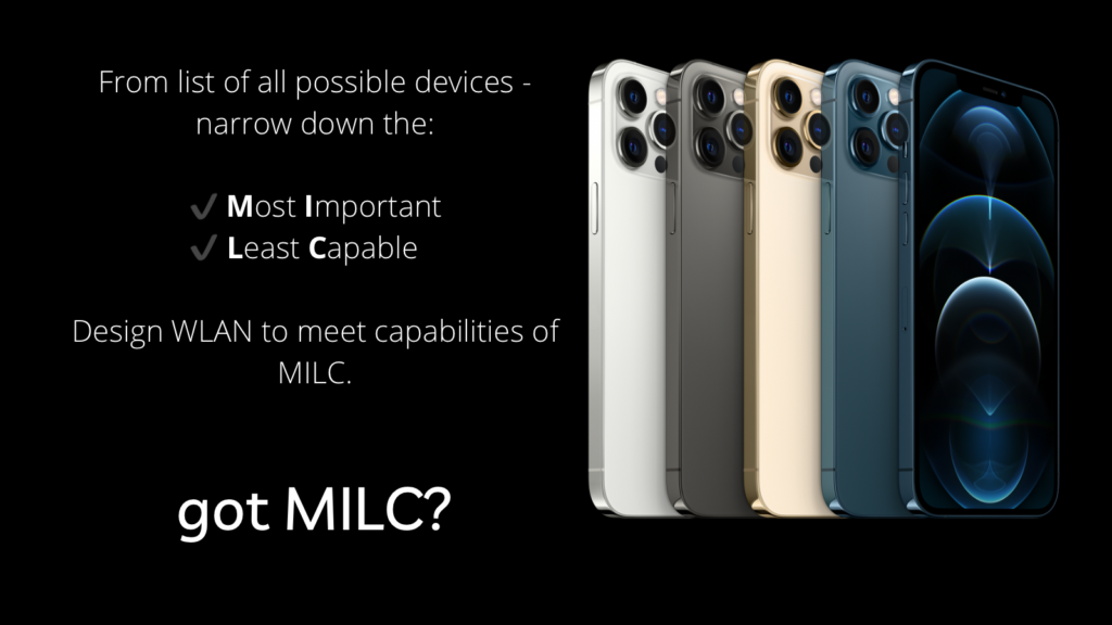
Your most important devices are suffering from it.
There’s a design philosophy that has governed enterprise wireless networking for nearly two decades. It goes by the acronym LCMI — Least Capable, Most Important.
The premise is straightforward: find the weakest Wi-Fi device your business cannot afford to lose — the infusion pump, the legacy barcode scanner, the aging POS terminal — and design your entire wireless network around its limitations. If that device stays connected, the logic goes, everything else will thrive.
It’s an elegant rule, and for legacy WLAN design, it was well-suited.
In the modern Wi-Fi era, it is quietly destroying the performance of your most valuable assets.
What LCMI Actually Does to Your Network
When you design a wireless network around your LCMI device, you’re not protecting that device. You’re systematically impeding every other device in the building.
Here’s the physics:
The Airtime Tax. Wi-Fi is a shared medium. When the least capable device transmits at a low data rate — say, MCS 0 at 6.5 Mbps — it occupies the channel for roughly 22 times as long as a modern Wi-Fi 6 device sending the same amount of data at MCS 11. In a mixed environment where legacy devices can represent 10–15% of your client population, they can consume 50–70% of your total channel airtime. Every Autonomous Mobile Robot (AMR), every VoIP badge, and every clinical tablet is waiting for that scanner to finish talking.
The Spectrum Problem. In the U.S., 57% of 5 GHz Wi-Fi channels require Dynamic Frequency Selection (DFS). Many legacy devices fail catastrophically when an AP changes channels during a radar event — they freeze, drop the connection, and require a reboot. So the LCMI response is predictable: disable all DFS channels, facility-wide. You’ve just cut your available channel pool by more than half. In a dense deployment, that’s the difference between a well-tuned micro-cell architecture and a co-channel interference catastrophe.
The Roaming Paradox. AMRs and VoIP handsets need to roam between access points in under 50 milliseconds. Legacy devices are notoriously “sticky” — they cling to a distant AP down to -80 dBm before roaming. When you tune your RF coverage to keep that sticky device connected, you inadvertently create the very cell overlap that causes ping-pong roaming for your fast-moving assets. Your AMR stops mid-aisle. Your nurse’s Vocera call drops in the hallway.
The Security Trap. Many legacy devices support only WPA2-TKIP, a security protocol that was deprecated in 2012. The 802.11 specification requires that any SSID supporting TKIP be limited to 20 MHz channel widths and that high-throughput modes be disabled. Keeping a single aging device connected can block your entire organization’s path to WPA3 and the security posture your compliance team demands. WPA2-only devices must be relegated to the 2.4 GHz and 5 GHz bands. Only modern Wi-Fi clients can take advantage of the 6 GHz band, which offers additional spectrum and requires robust security. When possible, enable WPA3 on the lower bands as well to support modern Wi-Fi clients on a spectrum diet.
The Real Problem: Modern Networks Have Multiple “Most Important” Devices
LCMI was designed for a world in which a single class of devices dominated the wireless population. That world no longer exists.
A hospital floor today simultaneously hosts infusion pumps, cardiac telemetry monitors, VoWLAN nursing badges, physician iPads, pharmacy delivery robots, and mobile imaging carts. A manufacturing floor runs legacy IIoT sensors alongside AMRs with sub-10ms latency requirements and machine vision systems streaming gigabytes of inspection data. A stadium hosts 55,000 consumer devices, legacy POS terminals, 4K broadcast production systems, and handhelds for venue operations.
Every one of those environments has multiple most important device cohorts with requirements that directly contradict each other:
- The infusion pump needs DFS disabled. The AMR requires all 16 DFS channels to be available for channel reuse.
- The legacy scanner needs low mandatory data rates. The VoIP badge needs high rates to prevent airtime starvation.
- The cardiac monitor needs 802.11r disabled (its driver crashes on those frames). The pharmacy robot needs 802.11r to achieve sub-50ms roaming.
LCMI tells you to pick one. Modern wireless design demands that the design serve all of them.
A Modern Approach: Parallel Reality Architecture
The alternative is a framework called Parallel Reality Architecture (PRA).
Instead of designing a monolithic network with one set of RF parameters applied uniformly to every device, PRA treats your physical space as a multi-layered RF canvas. Different device cohorts are isolated, managed, and optimized independently across dedicated spectrum segments. From each device’s perspective, the network appears purpose-built for its specific needs — because it is.
The architecture has four layers:
Layer 1 — The Legacy Utility Layer (2.4 GHz)
Your oldest, most constrained devices — basic IoT sensors, legacy BYOD, older scanners without a 5 GHz radio — live here. Coverage-oriented design. Best-effort service. Critically: isolated from your mission-critical spectrum.
The containment layer. Legacy overhead stays here, never contaminates upper realities.
Layer 2 — The Life-Critical Stability Layer (5 GHz non-DFS)
Your genuinely important but technically fragile devices — infusion pumps, cardiac monitors, legacy clinical scanners, VoIP badges — get a dedicated, DFS-free, stability-first RF environment. 802.11r (FT) is sometimes disabled here because those devices crash on it. That’s fine. These devices don’t move fast enough to need it. There is also a chance that these devices do not support 802.1X and gain no benefit from enabling FT. Lastly, it may be necessary to disable 802.11k & 11v on this SSID as well to support legacy clients.
DFS events on Layer 3 are invisible here. Infusion pumps never see a channel change.
Layer 3 — The Operations and Automation Layer (5 GHz DFS)
Because your fragile legacy devices are safely isolated in Layer 2, all 16 DFS channels are now available to your AMRs, modern VoIP handsets, and mobile workstations. 802.11r, 802.11k, and 802.11v are all enabled and tuned for sub-50ms roaming. Cell sizing is optimized for fast-moving clients, not sticky legacy devices.
Full DFS spectrum is unlocked because fragile devices are isolated in Layer 2.
Layer 4 — The High-Throughput Enterprise Layer (6 GHz)
Modern laptops, high-resolution medical imaging carts, and enterprise workstations operate in a clean spectrum that legacy devices cannot physically access. No airtime tax. No DFS concerns. WPA3 mandatory. Wide channel widths (40 –160 MHz) that are often impractical in the crowded 5 GHz band become routine. Aim to connect modern 6 GHz–capable Wi-Fi devices at Layer 4. Having said all this, at sufficiently high density, you may need to step down to 20 MHz at 6 GHz.
The ultimate clear-air lane. No airtime tax. No legacy overhead. Ever.
As a result, the infusion pump and the pharmacy robot are never in the same RF environment. The design constraint of one cannot compromise the performance requirement of the other. Be aware that the WNICs in many healthcare-related devices are very old. The reason is that upgrading any hardware requires an FDA certification review, and the company submitting the review is on the hook for the cost. Healthcare device manufacturers with integrated WLAN capabilities are disincentivized to update and refresh the WNICs in their devices
What This Looks Like in Practice
In a hospital applying PRA, a radar event during a storm triggers a Layer 3 DFS channel switch. The pharmacy robot and the nurses’ VoIP badges handle it seamlessly — their modern chipsets process the Channel Switch Announcement in milliseconds. The infusion pumps in Layer 2 never see the event. It’s invisible to them.
In a manufacturing facility, the legacy PLC sensors sit in Layer 1/2 with conservative channel assignments. The AMR fleet navigates on Layer 3 with aisle-optimized directional cells, full DFS spectrum, and fast roaming configured to trigger at -68 dBm — before performance degrades, not after. When an AMR rounds a corner, the roam happens cleanly, predictably, every time.
In a stadium, legacy PoS terminals at concessions are isolated in a perimeter-coverage layer with power levels deliberately attenuated inside the bowl. The 60,000-device attendee swarm and the press box production teams each inhabit independent, optimized realities in the same physical building. The venue can sell SLA-guaranteed premium wireless to exhibitors because the 6 GHz layer is physically immune to attendee swarm interference — and that becomes a revenue line item.
The Shift in Mindset
LCMI asks: “What is the worst device I have to accommodate?”
PRA asks: “What are the distinct capability profiles in my environment, and how do I architect an independent, optimized RF reality for each one?”
This is not a marginal tuning change. It is an architectural philosophy shift. It requires a more thorough upfront device audit, more deliberate spatial zoning, and a willingness to manage four logical RF environments instead of one. Modern enterprise wireless infrastructure — tri-band APs, controller-based radio management, 6 GHz spectrum availability — makes this not just possible but increasingly the expected standard of practice.
The LCMI philosophy protected the weakest device at the expense of the most capable. In an era when your highest-value assets — autonomous robots, real-time clinical systems, production-grade AV — depend on wireless connectivity for their core function, that trade-off has reversed.
“Your network should be stratified. Your legacy devices should be accommodated. Your modern devices should not be penalized for their coexistence.”
That is the promise of Parallel Reality Architecture — and it is worth demanding from every wireless design delivered to your organization in the modern era of Wi-Fi design and beyond.